Overview
- Contact formulation based on weak collocation (2D and 3D)
- Comparison of collocational and integrational methods
- Dynamic calculation: modified discretization in space and time
Project description
The scientific examination of contact analysis was first done by Heinrich Hertz in 1882. His analytical studies are fundamental for today's contact mechanics. Since analytical solutions exist only for very simple problems, numerical methods are primarily used for solving structural mechanics problems in contact, e.g. crash problems. Among various numerical methods, the finite element method is used that solves the governing equations in a weak sense. To this end, the structure or component is designed in a CAD software and then discretized into finite elements for the analysis. In this discretization step an approximation of the true geometry is usually performed with simple and mostly linear segmented curves. Therefore surfaces are characterized by plane segments, which complicates the formulation of contact conditions between bodies. This could lead to non-smooth movements or clamping of the bodies which results in non-physical solutions and numerical instabilities (upper video on the right). To avoid this problem a recently developed method, the isogeometric analysis, is used as an alternative (lower video on the right). It utilizes the function space of the CAD geometry for the finite element analysis. In this method the smooth surface is retained. However, the simple polynomials are replaced by non-uniform rational B-splines (NURBS). This new research field has been opened and offers opportunities for innovative ideas.
In this project, a stable and powerful isogeometric contact element is developed. Apart from static problems, a stable time integration method is proposed to allow dynamic analyses.
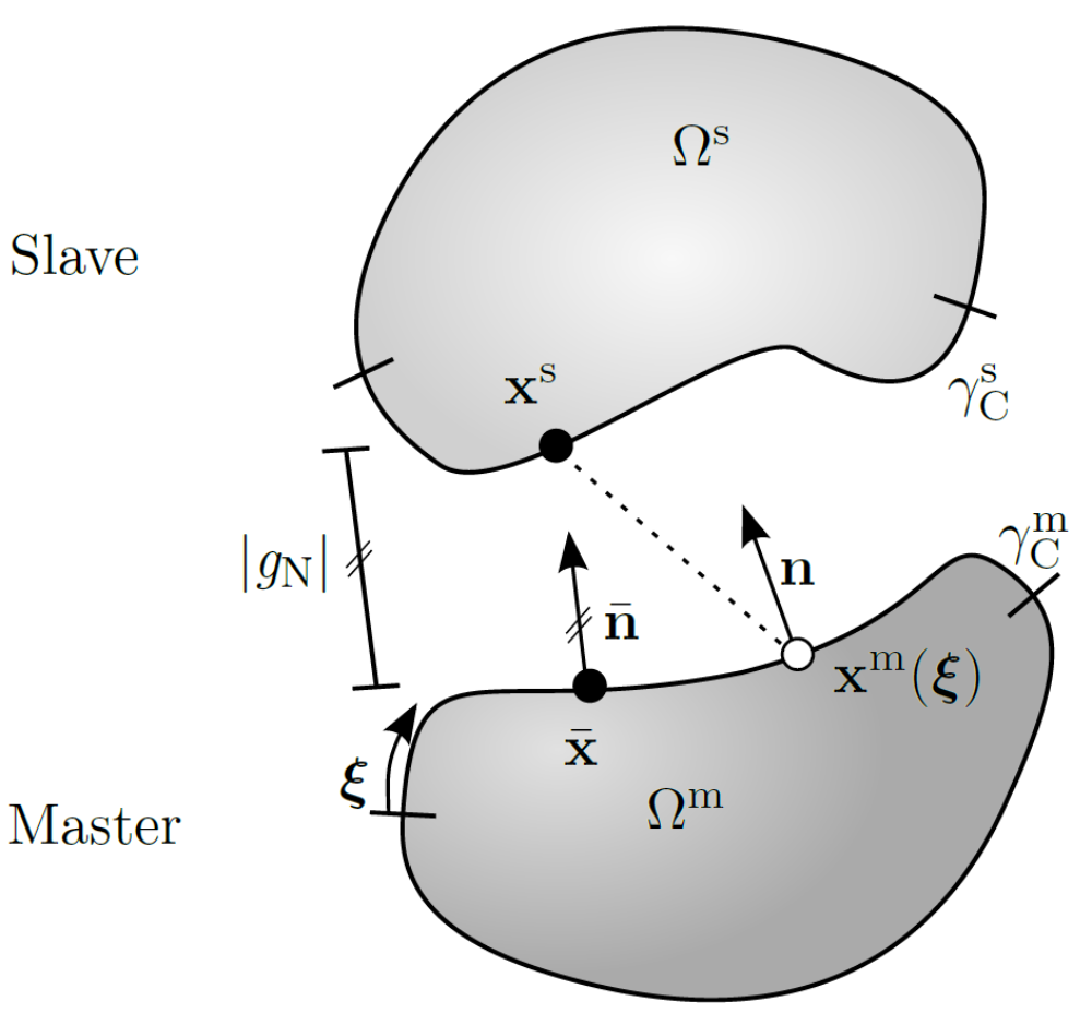
To prevent bodies from passing through each other, the so-called non-penetration conditions are formulated. The minimum distance between two bodies indicates whether regions are penetrated or not. In the classical "one-pass"-algorithm the bodies are divided into a slave and a master body. The distance is measured from the slave to the master side, using the normal perpendicular to the master surface.
In case of a negative distance, contact stresses are activated that push the penetrated regions apart. For rough surfaces, tangential relative movements result in tangential contact stresses. These stresses are restricted by Coulomb's friction law in sliding. For normal and tangential contact, the constraints can be summarized by the Kuhn-Tucker-Karush conditions. In a next steps the strong form of the contact constraints is transformed to a weak integral form to be included in the finite element approach. The conditions perpendicular to the surface are treated with the Lagrange multiplier method. This introduces new unknowns for an exact fulfillment of the non-penetration condition. For frictional contact in tangential direction, the penalty method is utilized by applying a penalty stiffness to comply with the used friction law. The highly nonlinear equations are linearized to generate a quadratic convergence behavior.
The obtained continuous virtual and linearized contact work must then be converted into a discrete form. This is done in two steps: Firstly, the continuous integrand of virtual and linearized contact work is discretized by inserting the discretized displacement and discretized Lagrangian multiplier. Secondly, the integral itself is converted into a sum over the evaluation points. This unimposing second step is the core part of the developed contact element. Depending on the number and position of the evaluation points, the contact conditions are satisfied pointwise or in an integral manner. In both cases the integrands remain unchanged. This enables the treatment of both pointwise and integral satisfaction in only one contact element.
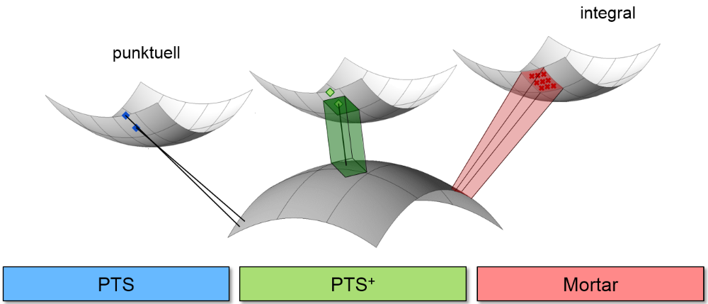
If the number of evaluation points corresponds to the number of control points of the slave surface, the procedure belongs to the group of collocational, punctual "Node-To-Segment" methods (see upper picture, blue). As the control points of isogeometric objects are not necessarily arranged on the geometry itself, special collocation points on the surface are used for the evaluation of the contact conditions. Amongst others these can be Greville, Botella or Chebyshev points. In this context the name "Point-To-Segment" (PTS) is suggested for the first version of the developed contact element. The non-penetration condition is exactly maintained at the collocation points. Contact forces prevent the penetration.
Applying weights to the collocation points enables the transfer from contact forces to contact stresses. These weights are defined once at the beginning of the simulation and remain constant throughout the simulation period. Especially in the case of frictional contact the weights have a positive influence on the evaluation of the friction law. This alternative method as a second version of the contact element is referred to as PTS+ (see upper picture, green).
Taking Gauss points for evalution transforms the contact algorithm into an integral version. The contact integral is integrated numerically. If the discretization of the slave and master surface implies the position of the Gauss points, a consistent segmentation is applied. Especially for curved structures the segmentation might become quite complex. Even without segmentation, the integration errors remain very small due to the smooth surface description with NURBS. Therefore the Gauss points are positioned on the slave surface for every slave element. In this third alternative the contact condition is fulfilled in an integral form. As all quantities are projected to the control points, it can be seen as a "Mortar" method (upper picture, red).
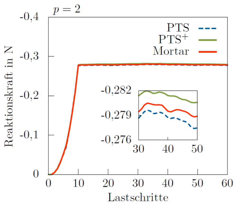
A comparison of the three contact element versions PTS, PTS+ and Mortar clearly shows that concerning the computational time for contact evaluation, the collocation methods turn out to be the winner. Since the computational time for contact linearly depends on the number the evaluation points, less evaluation points require less time. Unfortunately, less evaluation points mostly lead to a lower quality of the results. However, numerical tests show, that the stress results of the Hertzian problem and the reaction forces in the ironing problem are of the same quality for the simple collocation approach as for the more expensive Mortar one. Consequently, taking into account the results with friction, the weighted collocation PTS+ appears to be the most efficient contact element version.

In order to use the contact element for dynamic calculations, a stable time integration method is required, which introduces an additional discretization in time. Therefore the simulated period is divided into small times steps. In a "single-step" algorithm, discrete values at the end of an interval are computed with the information from the last and current time step. If no knowledge of the current time step is required, an explicit method is created. Values of the current time step can be estimated without solving any system of equation. Unfortunately, the process is only conditionally stable.
Therefore, an implicit method is utilised in this work, which takes information of the last and current time step into account. The Newmark method is used as the basic time integration scheme, which is modified by dividing the acceleration into a contact and non-contact part. The contact acceleration is dissipatively modified to consider only accelerations of the last time step. The energy of the system becomes stable, but oscillations occur in the contact forces. The reason can be found in the disproportion between the acceleration and the mass of the contact point. Due to contact, the control points of the surface are abruptly diminished, and as a result singular accelerations occur. Since the control points are associated with mass, singular inertial forces arise, which lead to oscillating contact forces. This phenomenon can be countered by removing the mass from the contact zone. Redistribution of surface mass is physically justifiable, since surfaces are considered infinitely thin and thus don’t possess mass. Technically, the surface mass is removed by redistributing perpendicular parts of the front shape function to shape functions of the control points inside the body. The control points of the contact surface become massless and oscillations of the contact forces disappear. Two possible redistribution scenarios are examined. In the first method shape functions belonging to control points of the surface are distributed equally to control points behind the surface. The second method takes special factors for redistribution, decreasing the order of the surface elements. Both methods proved to be targeted and adequate and when combined with the dissipative Newmark algorithm yield to a stable time integration scheme.
Project data
Project titel:
NURBS-FEM für Kontaktprobleme
Funding:
German Research Foundation (DFG), Research Grant BI 722/8-1, GEPRIS project number 212273885
Researcher:
Martina Matzen
Publications
- Matzen, M. E., & Bischoff, M. (2017). A weighted point-based formulation for isogeometric contact. Computer Methods in Applied Mechanics and Engineering, 308, 73–95. https://doi.org/10.1016/j.cma.2016.04.010
- Tkachuk, A., Matzen, M. E., Kolman, R., & Bischoff, M. (2017). Singular mass matrices for isogeometric finite element analysis of dynamic contact. Proceedings of the 7th GACM Colloquium on Computational Mechanics for Young Sci-Entists from Academia and Industry, M. Von Scheven, M.-A. Keip and N. Karajan (Eds.), Stuttgart, Germany, October 11-13. https://doi.org/10.18419/opus-9334
- Matzen, M. E. (2015). Isogeometrische Modellierung und Diskretisierung von Kontaktproblemen [Doktorarbeit, Bericht Nr. 64, Institut für Baustatik und Baudynamik, Universität Stuttgart]. https://doi.org/10.18419/opus-642
- Matzen, M. E., Cichosz, T., & Bischoff, M. (2013). A Point to Segment Contact Formulation for Isogeometric, NURBS Based Finite Elements. Computer Methods in Applied Mechanics and Engineering, 255, 27–39. https://doi.org/10.1016/j.cma.2012.11.011
- Matzen, M. E., Cichosz, T., & Bischoff, M. (2012). Point to Segment Contact Formulation for isogeometric NURBS FEM. Proc. YIC 2012, First ECCOMAS Young Investigators Conference, A. Andrade-Campos, N. Lopes, R.A.F. Valente and H. Varum (Eds.), 24–27 April 2012, Aveiro, Portugal.